Cable Option

Features

  • Current amplification enables to drive relay, solenoid valve or small motor, etc directly.
  • Signal conversion enables applying to any system.
  • Standard positioning of cable option shall be 100mm far from the sensor head.(Custom configuration is availablae.)


cable op 22

Common specifications

       Mode                             Function                             Output form     Maximum load Indicator
CAL-01 Add indicator

NPN

N.O.

   DC24V / 15mA          Red LED      
CAL-02 Add indicator

NPN

N.O.

DC24V / 15mA
CAL-04 Add indicator

NPN

N.O.

DC24V / 15mA
CAB-N1

N.O.→N.C. conversion

Current amplification

NPN

N.C.

DC24V / 80mA

CAP-P1

NPN→PNP conversion

Current amplification

PNP

N.O.

DC24V / 80mA

CAP-N1

Current amplification

NPN

N.O.

DC24V / 80mA

CAB-P1

N.O.→N.C. conversion

NPN→PNP conversion

Current amplification

PNP

N.C.

DC24V / 80mA

N.O. : Normally Open

N.C. : Normally Closed

ModelDimensions(mm)Connection examples (Circuit diagrams)

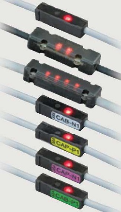
CAL-01

(Add indicator)

cal 01 zu 22

 cal 01 cnc 22

CAL-02

(Add indicator)

cal 02 zu 22

cal 02 cnc 22 

CAL-04

(Add indicator)

cal 04 zu 22

 cal 04 cnc 22

CAB-N1

(N.O. → N.C.)

(15mA → 80mA)

cal 01 zu 22

 cab n1 cnc 22

CAP-P1

(NPN → PNP)

(15mA → 80mA)

cal 01 zu 22

 cap p1 cnc 22

CAP-N1

(15mA → 80mA)

cal 01 zu 22

 cap n1 cnc 22

CAB-P1

(N.O. → N.C.)

(NPN → PNP)

(15mA → 80mA)

cal 01 zu 22

 cab p1 cnc 22

<Precautions>

・CAB-N1 : When used with sensors orswitches that have built-in indicator lights,built-in indicator lights cannot be used.

・CAP-P1 : Cannot be used with an output 80mA sensors or switches for standard operation.

・CAP-N1 : Cannot be used with an output 80mA sensors or switches for standard operation.

・CAB-P1 : Cannot be used with an output 80mA sensors or switches for standard operation.